4 Transformers Thermography/ Ultrasound- Green hills Mall


Choy and I were called in on May 14th to speak with management of this mall regarding issues with their electricity.
I got text from Choy on a Power Quality report a couple of nights prior. I would like to somehow post this document onto this blog for posterity but I don't think I can. When I read it, I didn't see a good report. The PQA settings configured for this job was incorrect and the data was corrupt. The waveform images that were attached to the report were also clipped (a straight line on the current waveform), so how can you possibly provide an accurate assessment of the electrical system if the data is bad? Actually, the funny part is that they even mentioned that the data may be corrupt and inaccurate in the actual report (their own report!) but still gave recommendations of what actions to take!
I am not here to trash on anyone's work. I did think, however, that this was a good learning experience. Seeing someone else's work can help you assess what your own value is to the industry and it provides markers on what I could improve on.
Our resident Power Quality Analyst, Hermz, Choy and I went to the mall office on May 14th. Hermz gave his presentation on the numbers and relayed (against the advice from other companies) that Harmonic filters are not needed for the facility.
They've been getting high current readings on the Neutral (more than 400% than usual) of one of the main transformers and that was one of the reasons for getting harmonic filters. When we collected our data, at most it was 132%. What we realized later was the CT for that transformer was wired wrong and it was giving a false reading. Up to this point, I don't understand how they haven't noticed it. A simple way to find out if your Meter is not giving you the correct numbers is to get an iFlex (FLUKE), put it around your Neutral, and compare the number on your clamp meter to the Meter. Up to this point, I don't understand how they didn't do that. It turned out that that was the reason for the high current readings. So, what turned out to be a suspicion of Harmonics causing higher current and overheating of the neutral was actually just faulty wiring of the Meter.
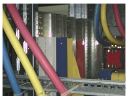
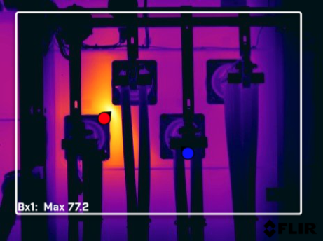
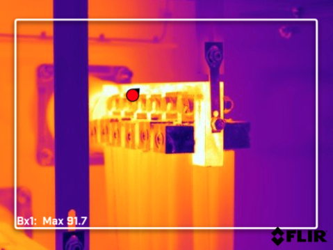
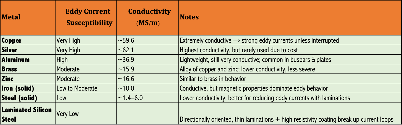
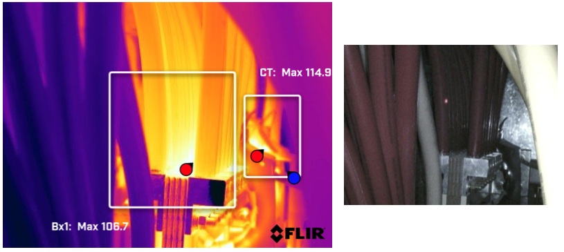
Ok! "But why is the neutral line on the secondary side of the transformer discolored?" they asked. Using our thermal camera we took an image.
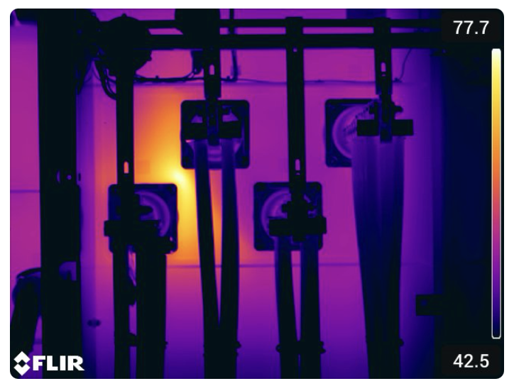
Turns out there is a connection issue inside their tank. High resistance connections are inefficiencies to an electrical system. High resistance conditions can range from loose connections, oxidation or corrosion, damaged strands, improper crimping to thermal degradation of components.
These things are never good and there is more of these than one can imagine in a single facility.
This increased electrical resistance restricts current flow, causes voltage drop and generates heat at the fault point. Thankfully we can see it clearly with a thermal camera!
Now the question I always asked for years is does it waste energy? If it turns a fault point into a hot point, then heat (or perfectly good energy) is dissipated into the environment. I suppose you can look at it like a fully air conditioned room and then opening the door and letting all that energy out.
It's a simple equation but P = I² × R, Ohm's law, makes it easy to calculate how much energy is wasted.
R for resistance is key here.
For example:
At a load current of 100A and contact resistance of just 0.1 ohms:
P = 100² × 0.1 = 1,000 W of continuous heat loss — that’s a 1 kW load you’re not using but still paying for.
Back to the story.
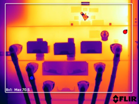
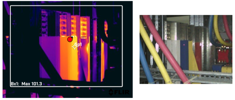
After walking through the Transformer/ Generator room to inspect the 4 transformers, I began my ultrasound inspection. Choy and Hermz were visually and thermographically inspecting the transformer together with the facility manager and the 3rd party maintenance manager as well as an entourage of engineers. They opened the back side of one of the LVSGs and they found one of the busbars with peeled insulation.
I'm not sure if the facility manager saw this but the 3rd party maintenance manager certainly did. I'm not sure if his eyes told surprise, anger, or sheer worry (for his job). They passed the inspection for this LVSG cabinet about a month ago!
The next night Choy and I returned and did a proper inspection. I worked on the ultrasound looking for partial discharge and Choy looked for more thermal anomalies. We found plenty of thermal anomalies and realized that this facility is not in good shape.
We are suspecting that eddy currents are being induced onto the metallic frame of the enclosure.
How do you suspect if it is eddy currents or not?
A good indicator is if you see unexplained hotspots appear on non-current-carrying metallic surfaces like support frames, busbar brackets, or enclosure walls.
I've noticed that these hot areas are near magnetic fields, such as around busbars, CTs, or tightly grouped conductors.
There are some metals that are more prone to eddy currents formation like aluminum and copper because they are strongly conductive.
Side thought: So why aren't copper or aluminum used as transformer core material if they are very conductive?
Transformers require core material that guides magnetic flux efficiently, not just conductivity. Steel is magnetic. Copper and aluminum are not. Steel is also conductive to eddy currents but not as much as copper and aluminum. Steel can also be laminated with insulation coating that will reduce eddy currents.
Copper and aluminum can be used as a core, from what I hear, but they are more expensive than steel per volume and require more specialized laminations to mitigate eddy currents and hysteresis loss.
Here is a ranking of metals susceptible to Eddy currents from most to least:
Are these eddy current conditions dangerous. Electrically it is not dangerous but there is a burn risk for people. Make sure you are wearing gloves.
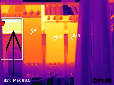
As mentioned before, the facility manager said that there is discoloration on the Neutral on the Secondary side of the Transformer. What he didn't know was there were many conductors--not only the Neutrals--that have discoloration. With the color white it is just more noticeable.
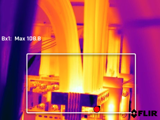
The maximum temp rating for these conductors are 90degC, written on the conductors themselves. You can see the discoloration already for this conductor. The snap judgement here would be a loose or corroded connection, but I think that is why visual inspections are just as important as having a thermogram. Is the issue really about a connection problem, or is it really the entire conductor itself that needs to be replaced? If you want to cut the ends and re-establish a good electrical contact again, based on the digital photo, you might have to cut back a foot and a half. But since there's no slack, you would have to replace the entire conductor. How much thermal stress do you think this conductor experienced? The only way to find out is to do an insulation resistance test and see the numbers (ohms) to determine its condition.
Let's get back to the equation P = I² × R.
If your neutral conductor carries 40A and there's a 0.05ohm resistance from a high resistance connection:
That means P = 40² × 0.05 = 80 watts per hour is wasted on a 12 hours daily operation. That's a 29kWh/ month of pure loss just on that one hot spot.
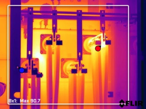
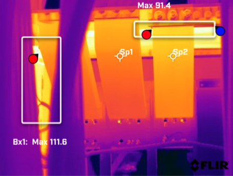
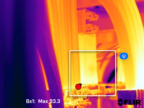
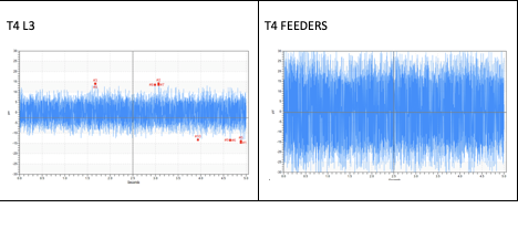
Here you can see something similar with elevated temperature between the conductors. On the right, there is a CT that is over heating. I found a lot of arcing from CTs here with my SDT340 ultrasound device.
I'll stop here for the thermal inspection. In total there were roughly 30 thermograms we took.
While Choy was taking images, I was roving around with my SDT340 using a FLEXID2 (wand) sensor.
I checked the Primary and Secondary side on the front of the transformer. For the Secondary side, I swept each Line, Neutral, and the feeders at the bottom going to the LVSGs.
I found very early signs of arcing or tracking. But based on the FFT, signs point to early signs of Corona. This is the one thing I am trying understand in my early experience with Ultrasound is distinguishing the difference between those three electrical issues. I have sound files (severe cases) for each issue and it seems like the ones I found are the Corona type. But can there be Corona in a 400V system? Some say yes but I want to get a body of evidence for this.
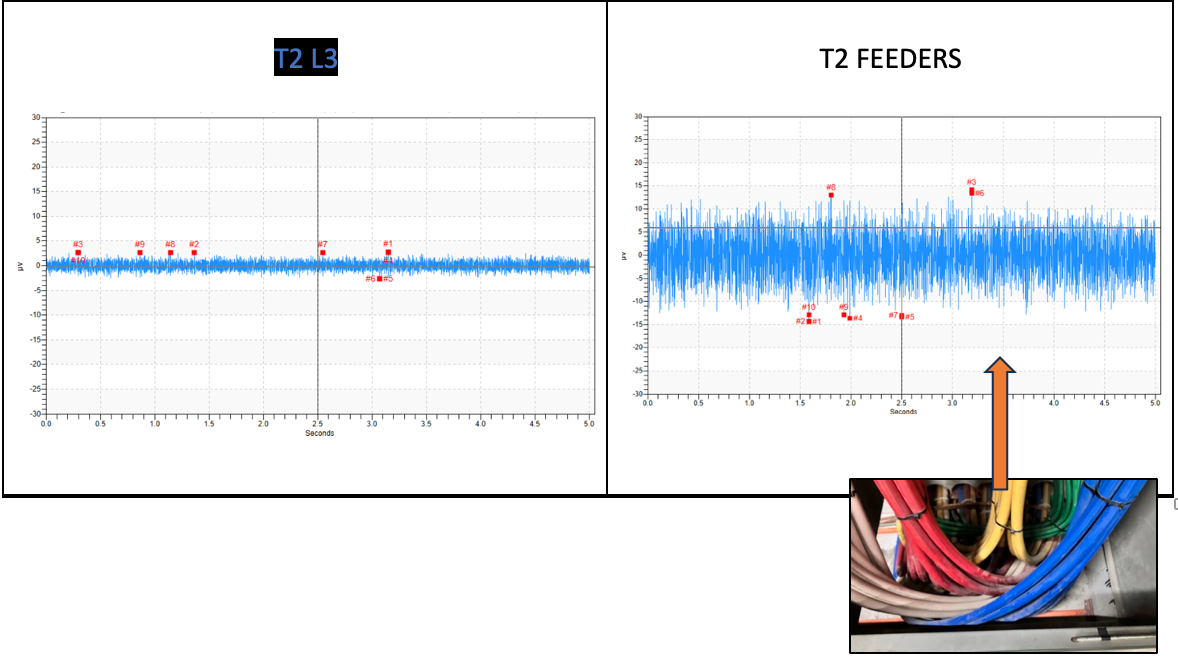
The bundling and the dust on the conductors are contributing to a partial discharge. Now, I haven't determine what kind of discharge or how. Is it because Line to Line conductors are touching against each other and there is a lot of amperage flowing through these conductors creating a magnetic field? Is there a cut in the insulation that I cannot see and there is some kind of ground fault or arcing? Does the failure of insulation inside of the conductor actually create some kind of fault that induces sound?
I don't know, yet.
There was not enough time to inspect all the equipment. Just a quick sweep. I learned that just finding issues is only good if you can communicate what you found exactly on what component and providing good analysis. Sometimes the environment or inspection point is too much of a safety risk to get any closer. In exchange, you cannot determine what exactly is producing high intensity sound.
The inspection ended and later we sent a thermographic report to the 3rd party maintenance manager. If the facility manager saw this report, he'd probably flip out and heavily question the maintenance manager's oversight. We did, however, send the ultrasound report, even if there were no findings that would be deemed critical.
In the Philippines, Ultrasound as condition-based monitoring tool is still close to an unknown. I am probably the only person in the country that has these tools, I reckon. So there's a large opportunity for education and experimentation. It'll be my purpose and pleasure to go through this journey of learning more about Ultrasound and bringing it to recognition as a dominant tool as part of Reliability Maintenance strategies.
--End--