Ground Faults on a Solar PV system

I received a notification from an engineer on Linkedin, Kevin John Esperila, on a issue with ground faults in his Commercial PV System.
Ground faults can be a common issue for solar PV systems, but tracking them can be difficult.
To find a ground fault you would first open the circuit on the combiner box. Then, measure V- to ground and V+ to ground. Whichever has the lower measurement, you would divide that number by the module Voc. The resultant number is the location of the ground fault.
Here is an example:
V+ to ground: 400V
V- to ground: -100V
Voc of module: 50V
100V/ 50 = 2
So, the ground fault may be located on the second module from the negative home run.
It is also good to do an insulation test on the cable run to check the condition of the conductor.
Kevin said that he did the test and mentioned one important point. The ground fault only appears when it rains.
That made a lot of sense and had me recall my time with Solar Philippines when I had similar encounters with inverters that would shut off and restart constantly. Quite an annoying fault, really.
He then posed a question: aren't the SPDs suppose to react to a ground fault?
And the answer to that is no. That's because ground faults are current related events. There is a voltage potential, but upon touching a grounded component (like the racking system) it bridges that gap and current flows. The "S" on SPD is "surge," and that should give one the thought of transient events and a voltage condition.
They do have GFDI (Ground Fault Protection devices) that are bonded between the negative and ground in a grounded system (which are older systems). On the other hand, now you have transformer less inverters (most all utility scaled systems) that have a floating ground. These systems can have a RCM (Residual Current Monitor) device that monitors any current leakage to ground and safely shuts off the system or string. There's also IMDs (Insulation monitoring devices) that constantly check insulation resistance to ground and safely shuts off the system or string.
If you think about it both are good to have because it gives you an indication of a ground fault and technicians can deal with it. However, it is still a problem and both devices do not tell you exactly where the ground fault is located. So you are back to square one.
Now a days, most utility scaled plants have a SCADA system so they don't need these devices to spot that something is wrong. All they will see perhaps (and I have not confirmed this but can imagine) is a downed inverter or low performing inverter.
Maintenance will still have to look at it, regardless.
Which means that possessing skills for locating ground faults will still be important.
Back to the ground fault issue that only appears when there is moisture or when it rains.
So what to do?
You can either wait till it rains again, or you can manufacturer a rain situation.
I proposed that maybe getting a spray bottle of distilled water and systematically spraying starting from the Negative or Positive home run would force a ground fault condition. While someone sprays, there will be someone with a multimeter checking if a voltage potential at either V+ and ground or V- and ground appears.
So what do you do if the ground fault originates from the module itself. Let's say that there is arcing inside the junction box or within the cells?
It will only be a ground fault if the fault has a path to ground. In this case, it might be helpful to thermographically check the bypass diodes and back sheet and see if there are anomalies. Another thing to do is visually check the modules for any cracks (a rare case) or charring (brown spots) on the cells or between each cells. Internal arcing itself doesn't necessarily mean ground fault but it can lead to one eventually when the material mechanically fails through stress.
Kevin also brought up a good point. Can the cause be mismatched MC4 connectors? Initially I didn't think so. But if you think about it, the quality of your MC4s will determine the tolerance and failure rate. What is the issue here, the quality of the connector or the quality of workmanship to install the connector? To me, I think it is more workmanship. Did you have a competent--and capable--person installing the connector? Capable meaning, did the person have the right tools. Too often I've seen connectors crimped with needle nose pliers. I've done it myself and they never maintain especially in conditions where current is higher than STC (>1000w/m2). What is the temperature rating of those pins, really?
I propose that there are a few novel tools that can be used. One is an I-V curve tracer. And the other is Ultrasound w/ a thermal camera.
For the I-V curve tester, it would only work if there was a ground fault present. If the ground fault is consistently faulted to ground, you can take a measurement and you should be able to clearly see the step shape of the voltage reading, since voltage is being diverted to ground.
The other is ultrasound. As mentioned before, by spraying distilled water onto the connectors, perhaps (I've never done it) you can hear small signals of arcing inside of the connector or quite possibly between a connector and the racking system if they were zip tied together.
In a future experiment, I would really like to do this. It would be the coolest thing.
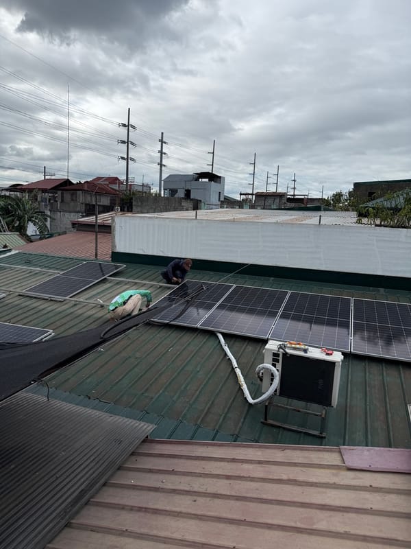
We have access to an I-V curve tracer from Mam. Tess so hopefully Kevin will agree to allowing us access to his solar PV system for a test. However, these kinds of ground fault tests are best done with utility scale pv systems because they are ground mounted and not roof mounted. With ground mounts you have clearance to be under them and don't need to disconnect mid or end clamps.
If we use the I-V curve tracer and do an experiment with ground faults, I'll post again.
--End--